Skip to Content
Ground source heat pumps

Quiet, consistent heat from the ground beneath your home.

A ground source heat pump uses a buried collector to draw low-temperature heat from the ground, then upgrades it for heating and hot water. Thermal Earth can coordinate the system design, ground array, drilling and installation as one accountable team.

No EPC? Send an enquiry or call 01269 833100. We can check the evidence needed for your property.

20+ years operating4,000+ systems installedIn-house drilling
Soughton House, a ground-source heat-pump project

Soughton House, one of Thermal Earth's ground-source projects.

Why consider ground source?

A long-term heating system designed into the property.

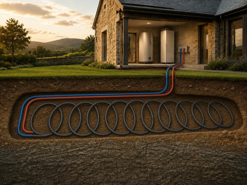
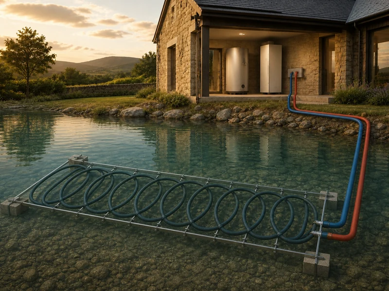
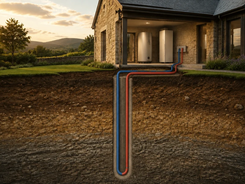
Ground source is worth assessing where the site can accommodate a borehole, horizontal collector or suitable water-source arrangement.

A stable heat source

Below the surface, ground temperatures vary less than outdoor air. The ground array gives the heat pump a dependable source that is assessed against the building's demand.

Most equipment stays out of sight

The collector is buried and the heat pump is normally indoors, avoiding an outdoor fan unit on the building.

Designed as one system

Collector, heat pump, emitters, hot-water storage and controls are designed together rather than selected in isolation.
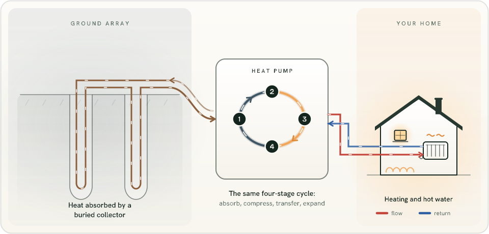
Diagram showing a closed loop buried in boreholes absorbing heat from the ground and feeding the four-stage refrigerant cycle that heats the home
How it works

From buried collector to comfortable rooms.

1

Collect

Fluid circulating through the ground array absorbs low-temperature heat from the surrounding ground or water source.

2

Upgrade

The heat pump's refrigeration cycle raises that heat to a useful temperature.

3

Distribute

Heating water supplies suitable radiators or underfloor heating and, when designed for it, a hot-water cylinder.
See how heat pumps work
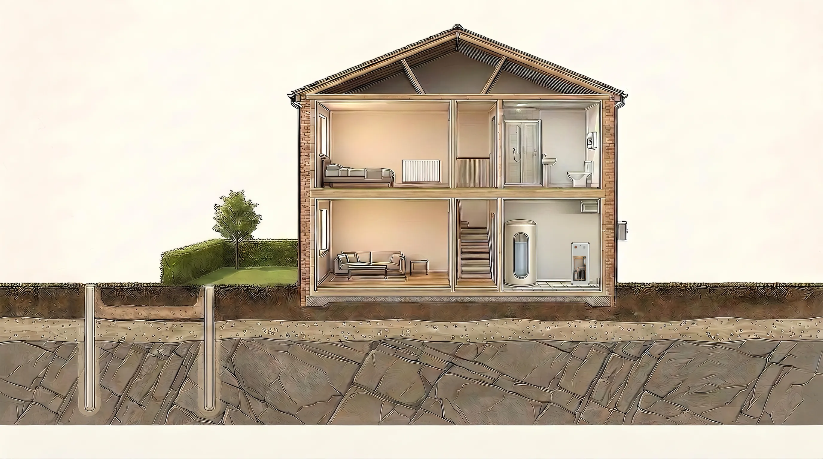
Flat cross-section of a two-storey UK home with the ground below it drawn in depth. Two boreholes are drilled deep into bedrock - typically 100 to 150 metres - shown at true scale near the surface and near the toe, with a labelled break where most of the depth is not drawn. A sealed loop of fluid leaves the heat pump cooled, runs west along a header trench, goes down one side of each borehole, turns round at the toe, comes back up warmed and returns to the machine. Inside the heat pump a separate sealed refrigerant circuit, shown both in the real service window and enlarged in a detail circle, raises the temperature using electricity, drawn as a separate angular amber cable. A third circuit of heating water carries the useful heat to underfloor heating, a first-floor radiator and the coil inside the hot-water cylinder, and returns cooler. The three circuits never mix.

Scroll the picture sideways to see all of it. Every label is written out below.

How a ground-source heat pump gets its heat from a borehole
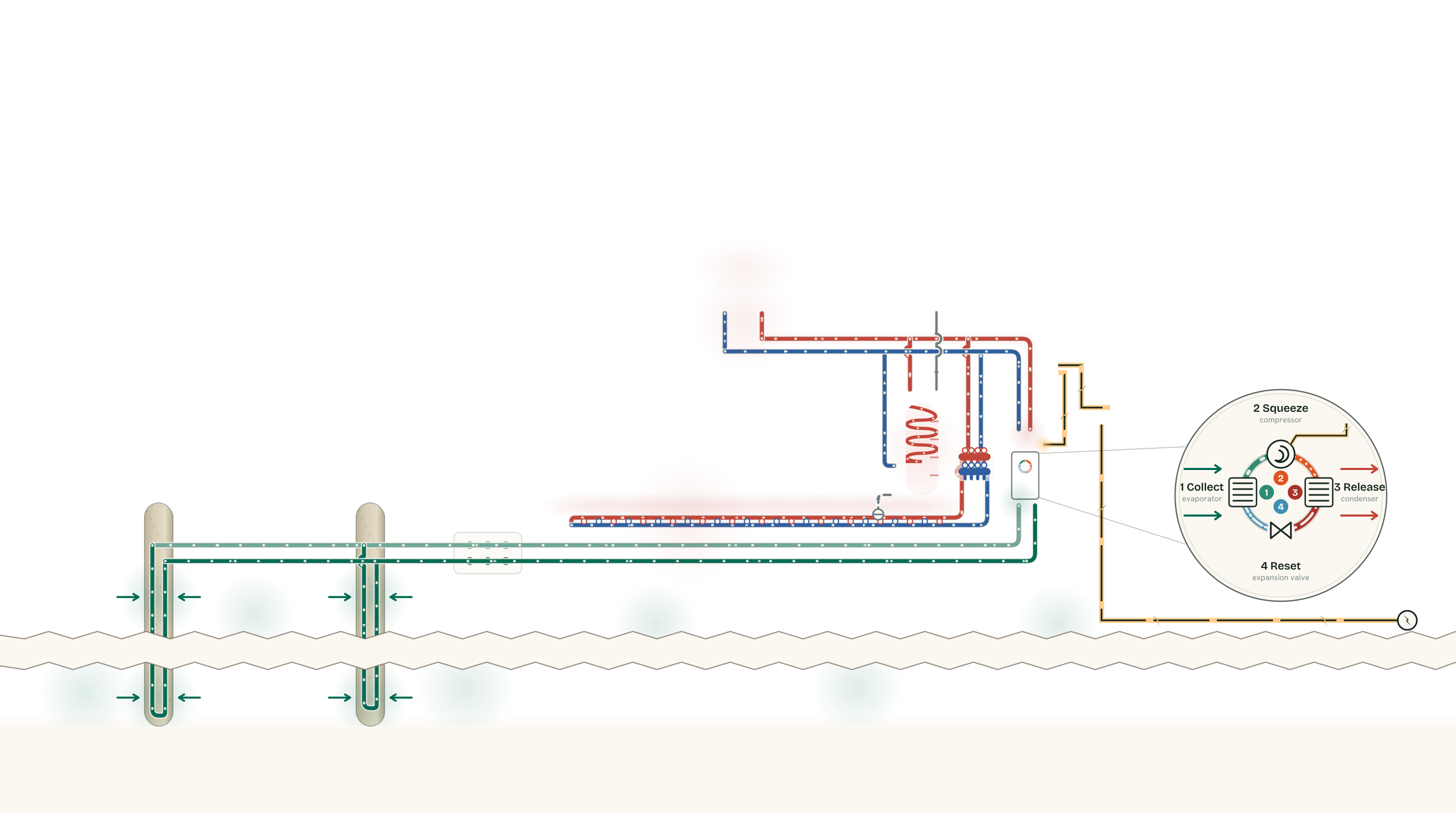
What is in the picture

  • Ground loop: cooled fluid down the boreholes, warmed fluid back Borehole, drilled and grouted; Header trench back to the house; A single loop of pipe goes down and comes back; The loop turns round at the bottom; Cooler fluid going back down; Warmed fluid coming up
  • Heating water: warm out to the home, cooler back Underfloor manifold; Hot-water cylinder; Heating coil - heating water never mixes with your tap water; Underfloor heating in the screed; Radiator; Warm water out; Cooler water back
  • Electricity from the grid to the compressor Electricity from the grid; Fuse board
  • Tap water, kept completely separate from the heating water Your shower and taps; Cold water mains
  • Refrigerant sealed inside the heat pump

The four steps inside the heat pump

  1. 1 Collect evaporator Environmental energy warms the refrigerant until it boils. It leaves as a warm gas at low pressure.
  2. 2 Squeeze compressor Electricity drives the compressor, squeezing that gas into a much smaller space. It leaves hot and at high pressure.
  3. 3 Release condenser The hot gas hands its heat to your heating water and condenses. It leaves as a hot liquid, still at high pressure.
  4. 4 Reset expansion valve A valve drops the pressure and the liquid flashes cold. It leaves as a cold mist, ready to collect more.
  1. A house, and two holes in the garden

    The house is drawn straight on. Under the lawn, two narrow shafts go straight down - you can see the top of one of them on the left, and the trench that carries the pipes back to the house.

  2. Down the borehole

    Each borehole is a single sealed loop: one pipe goes down, turns round at the bottom, and comes back up. Most of the depth is not drawn here - the torn band is where the drawing admits it. They are typically 100 to 150 metres.

    • Borehole, drilled and grouted
    • A single loop of pipe goes down and comes back
  3. The turn at the bottom

    Below the torn band the drawing is at true scale again - that is what the dimension down there is for. This is the U-bend at the toe of the bore. Nothing is taken out of the ground and nothing is put into it.

    • The loop turns round at the bottom
  4. Back to the house in one shallow trench

    Two pipes run side by side in a single trench: the cooler one on its way back down to the boreholes, the warmed one on its way in. The cooler pipe is deliberately drawn shallower, which is why nothing has to cross anything.

    • Header trench back to the house
    • Cooler fluid going back down
    • Warmed fluid coming up
    • Underfloor heating in the screed
  5. Where the loop meets the machine

    The warmed fluid comes up into the base of the heat pump and the cooled fluid goes straight back down. It never meets the water in your radiators - the two circuits only ever touch through a metal wall.

    • Underfloor manifold
    • Fuse board
    • Hot-water cylinder
    • Heating coil - heating water never mixes with your tap water
    • Cold water mains
  6. Inside the machine: four steps, over and over

    This is the only part of the whole picture that uses electricity. A sealed refrigerant goes round and round, and at each of the four stations it visibly changes.

    • Electricity from the grid
    1. 1 CollectevaporatorEnvironmental energy warms the refrigerant until it boils. It leaves as a warm gas at low pressure.
    2. 2 SqueezecompressorElectricity drives the compressor, squeezing that gas into a much smaller space. It leaves hot and at high pressure.
    3. 3 ReleasecondenserThe hot gas hands its heat to your heating water and condenses. It leaves as a hot liquid, still at high pressure.
    4. 4 Resetexpansion valveA valve drops the pressure and the liquid flashes cold. It leaves as a cold mist, ready to collect more.
  7. Where the heat actually goes

    Warm water runs to the pipes buried in the ground-floor screed, up to the radiator, and through a sealed coil inside the hot-water cylinder. Your tap water never touches it.

    • Radiator
    • Warm water out
    • Cooler water back
    • Your shower and taps
  8. Three separate circuits. Heat passes between them; the fluids never mix.

    Ground loop heat crosses here Refrigerant heat crosses here Heating water

    The loop in the ground is sealed, and so is the refrigerant inside the machine. Nothing from the borehole ever reaches a radiator or a tap.
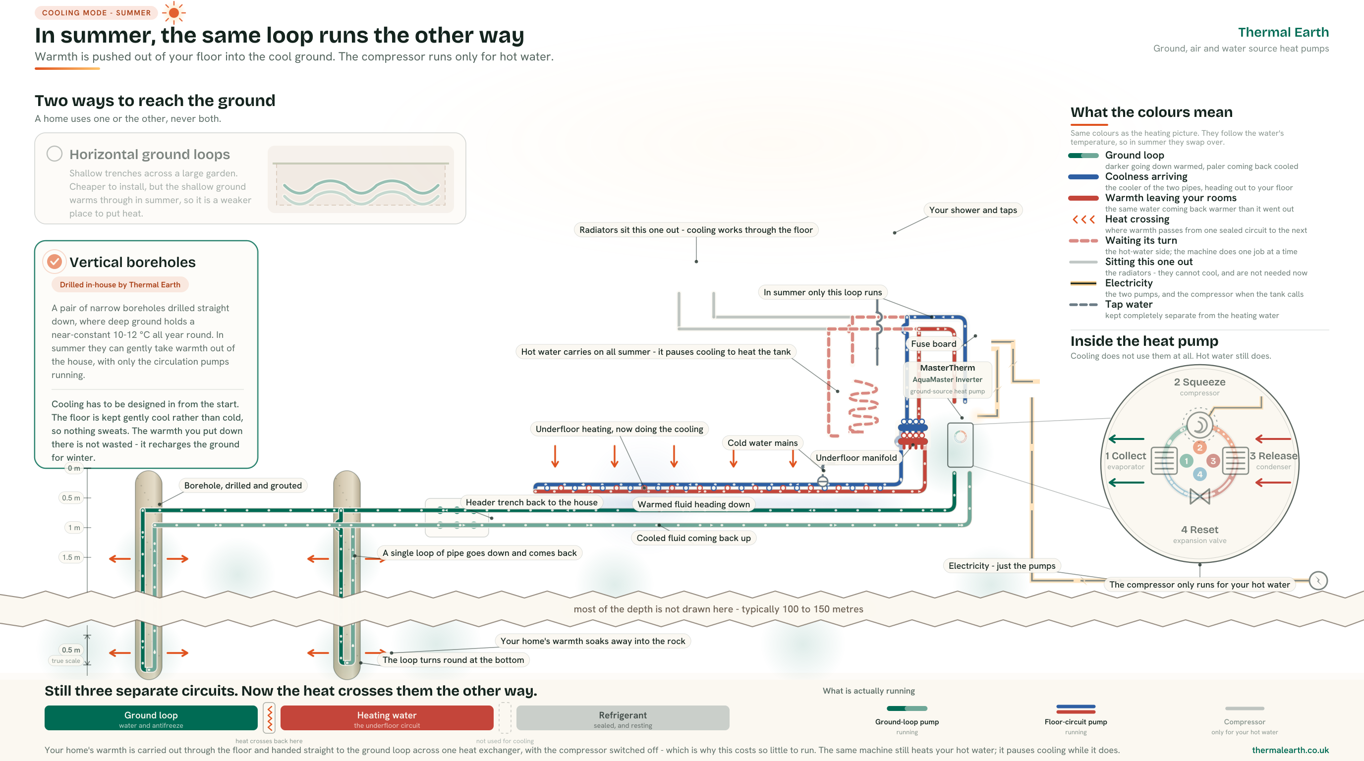
The same flat cross-section as the heating illustration, showing the summer mode of the same system. Two boreholes run deep into bedrock - typically 100 to 150 metres - drawn at true scale near the surface and near the toe, with a labelled break where most of the depth is not drawn. The sealed ground loop now leaves the heat pump carrying warmth from the house, goes DOWN one side of each borehole where short arrows show that warmth passing out into the rock, and comes back up cooler. Inside the house the underfloor circuit sends cool water out to the floor and receives it back warmer, so the colours of the two pipes are the reverse of the heating picture: colour follows the water's temperature. The radiator branch is drawn grey and still, because radiators cannot cool. The hot-water cylinder and its coil are drawn in the hot-water colour but dashed and without moving speckles, because the cylinder is still heated by this machine all summer - the machine simply pauses cooling and runs its compressor for a while to do it, rather than doing both at once. During cooling itself the compressor is off and only the two circulation pumps run. The three circuits still never mix.

Scroll the picture sideways to see all of it. Every label is written out below.

How a ground-source heat pump cools the same house in summer - passive cooling

What is in the picture

  • Ground loop: warmed fluid down the boreholes, cooled fluid back Borehole, drilled and grouted; Header trench back to the house; A single loop of pipe goes down and comes back; The loop turns round at the bottom; Cooler fluid going back down; Warmed fluid coming up
  • Floor circuit: cool water out to the floor, warmer water back Underfloor manifold; Hot-water cylinder; Heating coil - heating water never mixes with your tap water; Underfloor heating in the screed; Radiator; Warm water out; Cooler water back
  • Electricity from the grid, running the pumps Electricity from the grid; Fuse board
  • Tap water, kept completely separate from the heating water Your shower and taps; Cold water mains
  • Refrigerant sealed inside the heat pump, resting

The four steps inside the heat pump

  1. 1 Collect evaporator Environmental energy warms the refrigerant until it boils. It leaves as a warm gas at low pressure.
  2. 2 Squeeze compressor Electricity drives the compressor, squeezing that gas into a much smaller space. It leaves hot and at high pressure.
  3. 3 Release condenser The hot gas hands its heat to your heating water and condenses. It leaves as a hot liquid, still at high pressure.
  4. 4 Reset expansion valve A valve drops the pressure and the liquid flashes cold. It leaves as a cold mist, ready to collect more.
Collector options

The right ground array depends on the site.

Available land, geology, access, environmental constraints and the building's calculated heat demand all influence the design.

A property-specific design

What our engineers assess.

Room-by-room heat loss

The building's fabric and design conditions establish the output required.

Ground and access

Geology, land area, services, access and working space inform the collector route.

Emitters and pipework

Radiators, underfloor heating and pipework are checked against the selected flow temperature.

Controls and hot water

Comfort settings, zoning, storage and hot-water demand are designed into the complete system.

One accountable team

Ground-array design and drilling, coordinated with the heating system.

Thermal Earth's in-house drilling capability means the borehole work is coordinated with the system it must serve. You have one team joining up feasibility, design, drilling, installation and commissioning.

  • Site-specific feasibility

    We assess access, constraints and likely collector options before detailed design.

  • Integrated responsibility

    The ground side and building side are designed to work together.

  • Ongoing support available

    Servicing and long-term support are available when you choose Thermal Earth's aftercare.
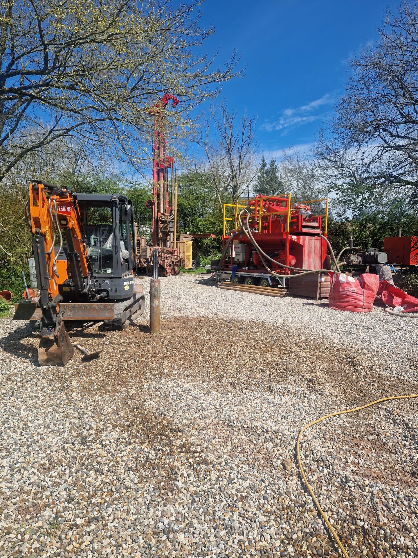
Thermal Earth drilling equipment installing a ground-source borehole
Cardiff Living homes at Brookfield Drive
Proven at project scale

Five boreholes. Thirteen individually controlled heat pumps.

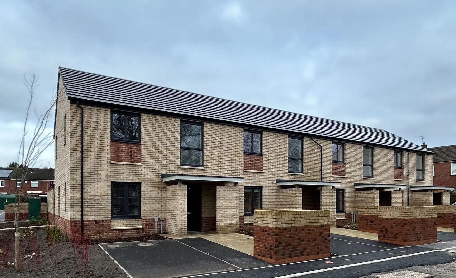
At Cardiff Living's Brookfield Drive scheme, five 150m boreholes serve 13 individual ground-source heat pumps, giving each home control of its own heating and hot water.

View the project
Running costs

Designed to lower bills, modelled for your property.

A correctly designed ground-source system can lower heating bills. The result depends on the building's heat demand, the fuel or system being replaced, electricity tariff, collector design, heating-water temperature, controls and how the property is used.

That is why we assess the property and complete system instead of promising a generic percentage saving.

Get a free estimate
Boiler Upgrade Scheme

Grant support may reduce the upfront cost for eligible properties.

Grant values and eligibility depend on the property, system and current scheme rules. Thermal Earth can check the route that applies and guide eligible customers through the installer-led process.

Common questions

Ground source, in plain English.

Not always. Horizontal collectors need suitable land, while vertical boreholes may suit a more constrained site if access, geology and permissions allow. A feasibility assessment establishes the realistic options.

Yes, where the radiators can deliver each room's required heat at the design heating-water temperature. Existing emitters are assessed and resized where necessary.

Some ground-source systems can provide active or passive cooling when the collector, heat pump, emitters and controls are designed for it. Cooling should be considered at the design stage rather than assumed later.

A well-designed system can lower heating bills, but the outcome is property-specific. We assess heat demand, the existing fuel, tariff, source design, emitters, controls and use before presenting an estimate.

Care for your heat pump.

Explore Comfort Care for annual servicing, remote monitoring on online-connected systems and priority support.

Explore Comfort Care

Planning for summer?

Ground source can provide passive or active cooling when specified for it. The equipment, pipework and controls need to be considered in the design.

Explore home cooling

Could ground source work for your property?

Start with a free estimate, then let our team assess the building, land and collector options.