Skip to Content
Water source heat pumps

Renewable heat from water, engineered around your site.

A suitable lake, pond, river or groundwater source can provide heating, hot water and, where the complete system is designed for it, cooling. Thermal Earth assesses the source, permissions and building together before recommending a route.

No EPC? Send an enquiry or call 01269 833100. We can check the evidence needed for your property.

20+ years operating 4,000+ systems installed In-house design and installation
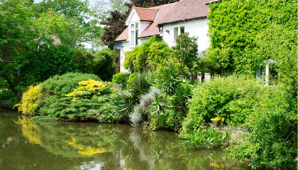
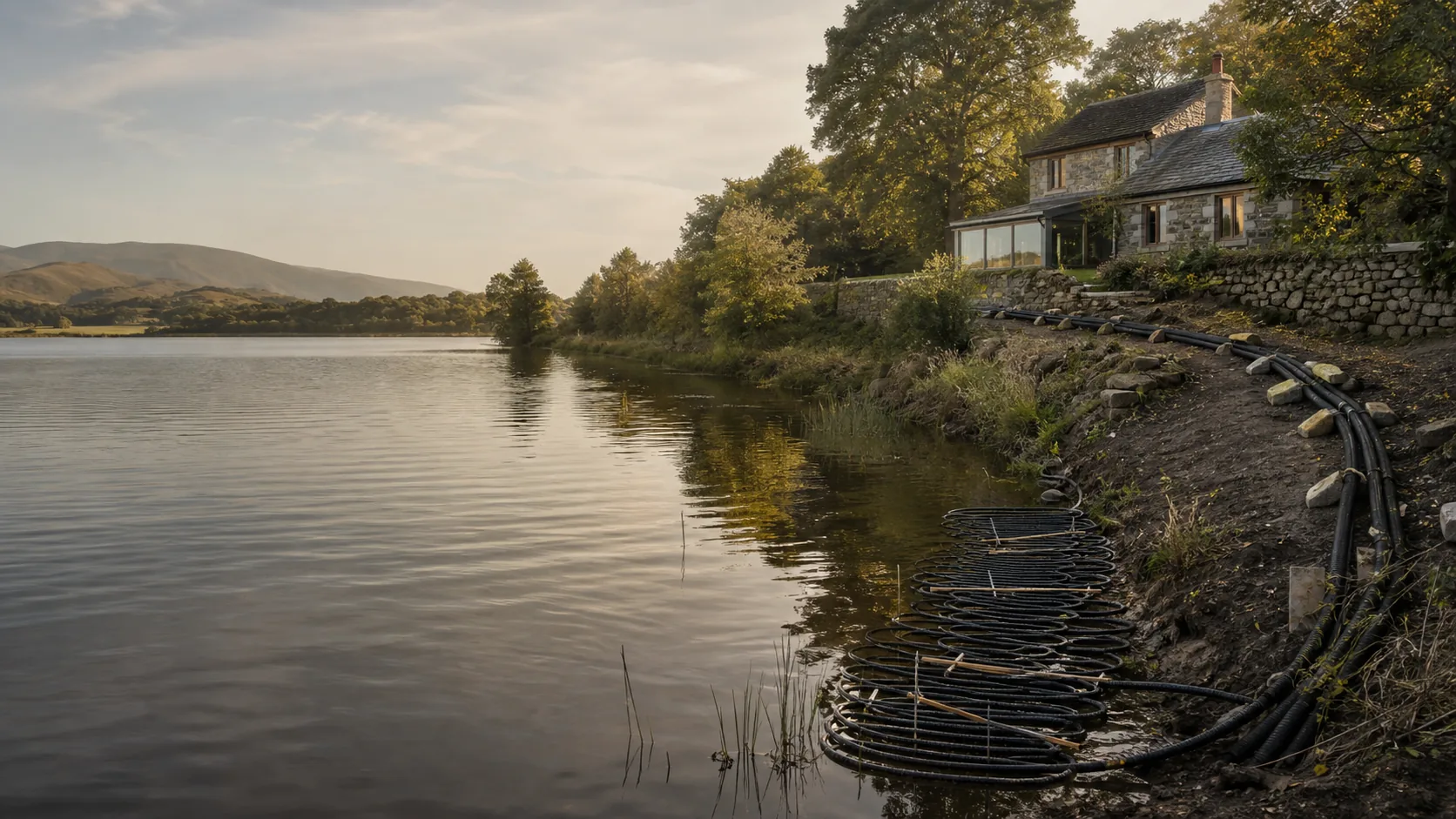
Illustrative lake-source heat-pump collector beside a rural Welsh home
Illustrative editorial visual. Every water-source system requires a site-specific design.
Choose the right route

Water source is not one standard system.

Source type, available flow or volume, water quality, access, environmental constraints and the building's heat demand determine what is practical.

How it works

Collect, upgrade and distribute.

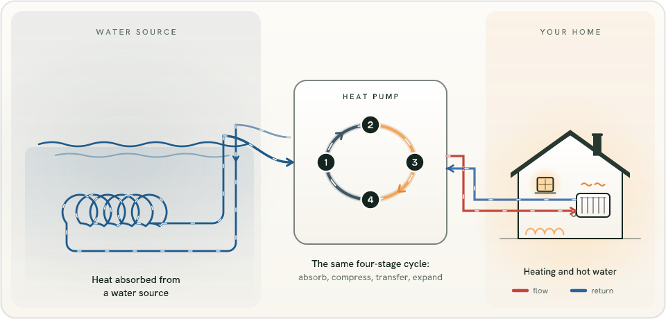
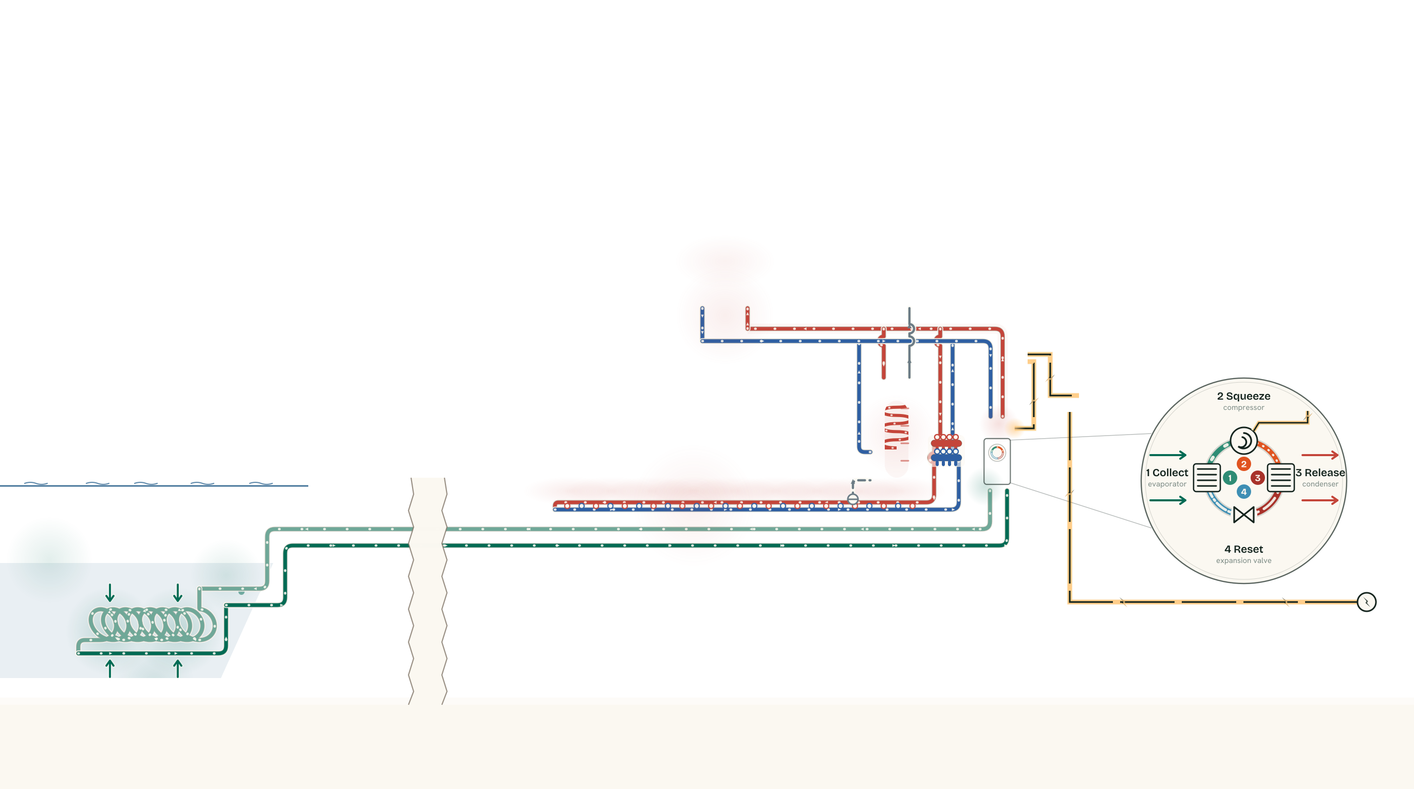
Diagram showing a submerged collector absorbing heat from a water source and feeding the four-stage refrigerant cycle that heats the home
  1. Collect

    A closed collector or an open-water arrangement transfers low-temperature heat from the source.

  2. Upgrade

    The heat pump's refrigeration cycle raises the captured heat to a useful temperature.

  3. Distribute

    The building system supplies suitable radiators, underfloor heating or hot-water storage, as designed.

See how heat pumps work
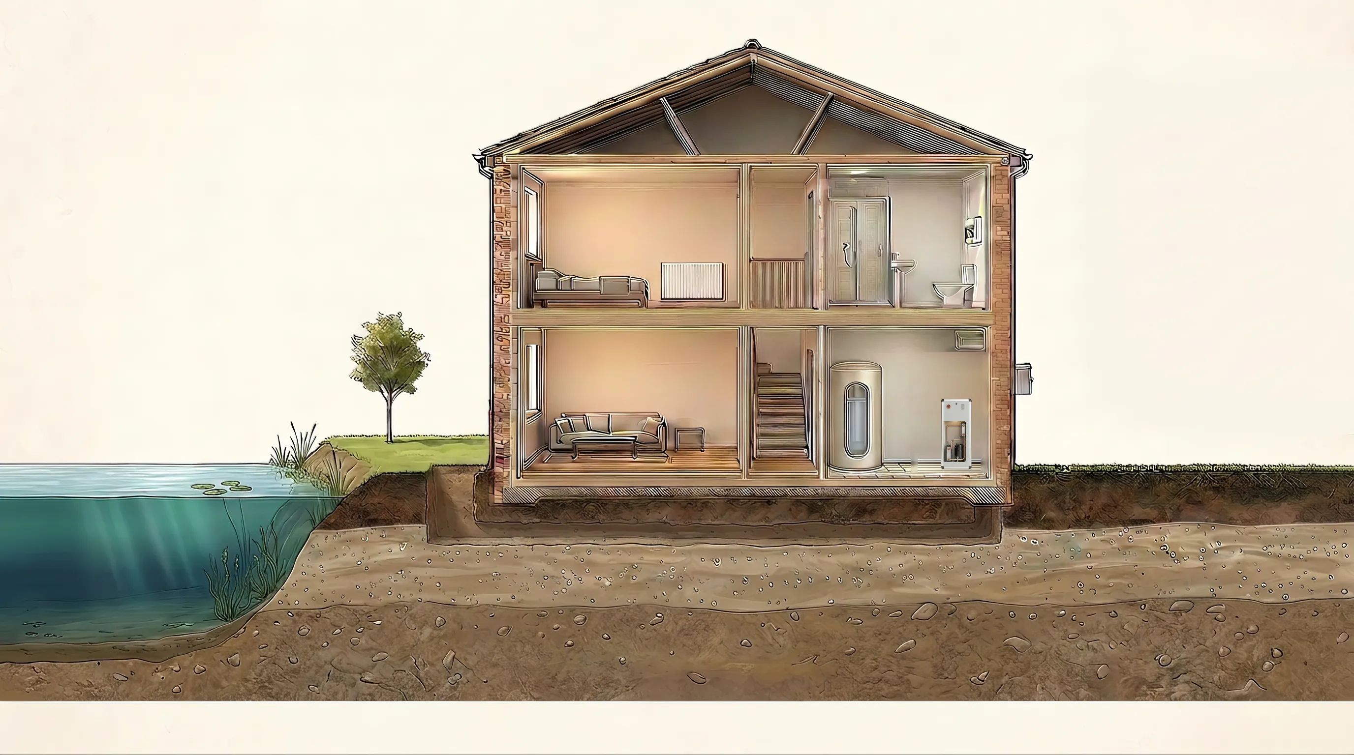
Flat cross-section of a pond on the left and a two-storey UK home on the right. A sealed coil of pipe lies on the bed of the pond about 2.4 metres down, wound into a long spring of 8 overlapping loops - a slinky - stretched out along the bed. The fluid goes out through the loops, turns round through a U-bend at the far end, comes back along a straight return leg beneath them, and both of its ends join a buried flow-and-return pair that runs to the house. A labelled break removes the 27 metres of ground between the bank and the house that cannot be drawn to scale. Nothing is taken from the pond; the water stays where it is and only its warmth crosses into the sealed pipe. Inside the heat pump a separate sealed refrigerant circuit, shown both in the real service window and enlarged in a detail circle, raises the temperature using electricity, drawn as a separate angular amber cable. A third circuit of heating water carries the useful heat to underfloor heating, a first-floor radiator and the coil inside the hot-water cylinder, and returns cooler. The three circuits never mix, and none of them contains pond water.

Scroll the picture sideways to see all of it. Every label is written out below.

How a water-source heat pump borrows warmth from a pond

What is in the picture

  • Source loop: cooled fluid out to the pond, warmed fluid back A single coiled pipe, sealed end to end; Warmth crosses the pipe wall; The loop turns round at the far end; Both ends join the pair; Buried trench to the house; Cooler fluid going out to the pond; Warmed fluid coming back
  • Heating water: warm out to the home, cooler back Underfloor manifold; Hot-water cylinder; Heating coil - heating water never mixes with your tap water; Underfloor heating in the screed; Radiator; Warm water out; Cooler water back
  • Electricity from the grid to the compressor Electricity from the grid; Fuse board
  • Tap water, kept completely separate from the heating water Your shower and taps; Cold water mains
  • Refrigerant sealed inside the heat pump

The four steps inside the heat pump

  1. 1 Collect evaporator Environmental energy warms the refrigerant until it boils. It leaves as a warm gas at low pressure.
  2. 2 Squeeze compressor Electricity drives the compressor, squeezing that gas into a much smaller space. It leaves hot and at high pressure.
  3. 3 Release condenser The hot gas hands its heat to your heating water and condenses. It leaves as a hot liquid, still at high pressure.
  4. 4 Reset expansion valve A valve drops the pressure and the liquid flashes cold. It leaves as a cold mist, ready to collect more.

Shown at all times: Heat pump.

  1. A house, and a pond at the bottom of the garden

    The house is drawn straight on. The pond is cut by the edge of the frame because it carries on; what matters is that the pipework between the two is buried and sealed the whole way.

  2. A sealed coil, lying on the bed

    One pipe, coiled and sealed at both ends, resting near the bottom of the pond where the water keeps its warmth longest. Both ends come back out together.

    • A single coiled pipe, sealed end to end
    • The loop turns round at the far end
    • Both ends join the pair
  3. Nothing is taken from the pond

    The water never enters the pipe and the fluid never enters the water. The pond is a little warmer than the fluid inside, so warmth crosses the pipe wall - and that is the whole of the exchange.

    • Warmth crosses the pipe wall
  4. Buried all the way to the house

    The pair of pipes leaves the bank and runs to the house in one shallow trench, the cooler one on its way out and the warmed one on its way in. The torn band is the drawing admitting how much of that run is not shown.

    • Buried trench to the house
    • Cooler fluid going out to the pond
    • Warmed fluid coming back
    • Underfloor heating in the screed
  5. Where the loop meets the machine

    The warmed fluid comes up into the heat pump and the cooled fluid goes straight back out to the pond. It never meets the water in your radiators - the two circuits only ever touch through a metal wall.

    • Heat pump
    • Underfloor manifold
    • Fuse board
    • Hot-water cylinder
    • Heating coil - heating water never mixes with your tap water
    • Cold water mains
  6. Inside the machine: four steps, over and over

    This is the only part of the whole picture that uses electricity. A sealed refrigerant goes round and round, and at each of the four stations it visibly changes.

    • Electricity from the grid
    1. 1 CollectevaporatorEnvironmental energy warms the refrigerant until it boils. It leaves as a warm gas at low pressure.
    2. 2 SqueezecompressorElectricity drives the compressor, squeezing that gas into a much smaller space. It leaves hot and at high pressure.
    3. 3 ReleasecondenserThe hot gas hands its heat to your heating water and condenses. It leaves as a hot liquid, still at high pressure.
    4. 4 Resetexpansion valveA valve drops the pressure and the liquid flashes cold. It leaves as a cold mist, ready to collect more.
  7. Where the heat actually goes

    Warm water runs to the pipes buried in the ground-floor screed, up to the radiator, and through a sealed coil inside the hot-water cylinder. Your tap water never touches it.

    • Radiator
    • Warm water out
    • Cooler water back
    • Your shower and taps
  8. Three separate circuits. Heat passes between them; the fluids never mix.

    Source loop heat crosses here Refrigerant heat crosses here Heating water

    Nothing is taken from the pond. The water stays where it is - only its warmth is borrowed, and none of it ever reaches a radiator or a tap.

Feasibility first

What our engineers assess.

A promising water source is the beginning of the design, not the conclusion.

Heat demand

Room-by-room or project heat loss establishes the heating output and source energy required.

Source conditions

Temperature, depth, volume or flow, seasonal variation and water quality inform the source design.

Permissions and ecology

Abstraction, discharge, closed-loop permitting and environmental requirements depend on the source and location.

Building integration

Heat pump, emitters, hot water, controls, electrical supply and cooling requirements are coordinated as one system.

Proven in the real world

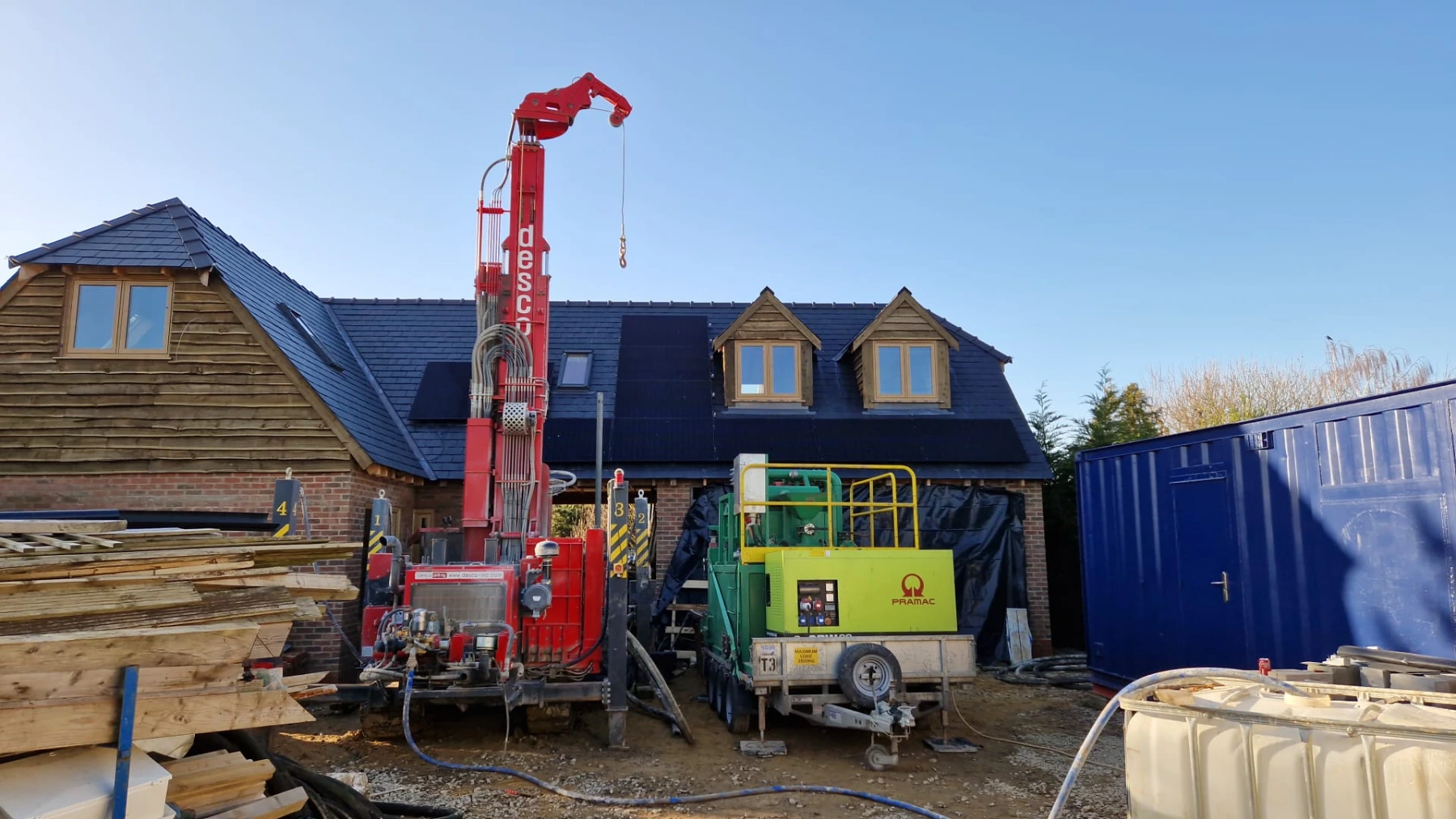
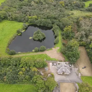
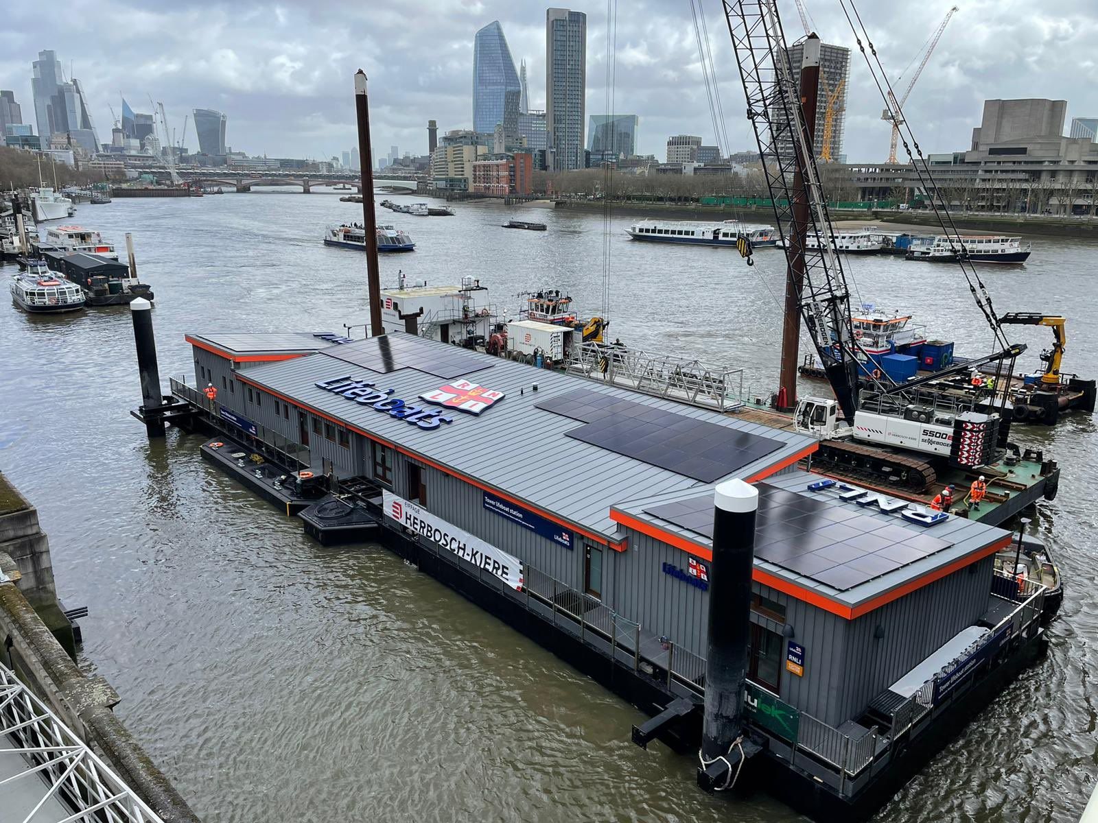
From a Carmarthenshire lake to the River Thames.

One accountable team

From source assessment to supported operation.

01

Assess

We review the building, source, access and likely environmental or licensing route.

02

Investigate and design

Testing and project-specific calculations establish the source and building-side solution.

03

Install and commission

Our team coordinates source works, heat pump, distribution, controls and commissioning.

04

Support

We explain operation, with servicing and lifetime support available if you choose us.

Boiler Upgrade Scheme

Eligible water-source installations may receive grant support.

Eligibility and grant value depend on the property, proposed system and current scheme rules. Thermal Earth can check the route that applies and guide eligible customers through the installer-led process.

Common questions

Water source, in plain English.

No. Available energy, seasonal conditions, depth or flow, water quality, access, ecology and permissions all affect suitability. We assess the source against the building's demand.

A closed loop circulates heat-transfer fluid through sealed pipework. An open system abstracts source water and returns or discharges it through a controlled arrangement. Their investigation, water-quality and permission requirements differ.

It depends on the source, location, system type and proposed abstraction or discharge. Closed-loop systems can also have permitting requirements. The correct route should be established before detailed works begin.

Some systems can provide active or passive cooling when the source, heat pump, emitters and controls are designed for it. Cooling is a design requirement, not an automatic feature of every installation.

Care for your heat pump.

Explore Comfort Care for annual servicing, remote monitoring on online-connected systems and priority support.

Explore Comfort Care

Planning for summer?

Some systems can provide active or passive cooling when the source, heat pump, emitters and controls are designed for it. Cooling is a design requirement, not an automatic feature of every installation.

Explore home cooling

Could your water source heat your building?

Homeowners can start with an estimate. Estates, businesses and complex sites can book a technical consultation.